on
How to build an Embedded Bootloader: Introduction
At ENLYZE, we deploy embedded sensor devices to our customers in order to measure electrical signals of their manufacturing appliances. We learned how frequent business requirements can change, so we decided early on that we must be a able to update those devices after initial deployment.
This series of blog posts will walk you through the main aspects of designing and implementing Over-The-Air updates for our sensors. Along the way, we will learn about the startup process of microcontrollers, programming internal flash memory and even dive into arcane realms such as linker scripts. 🧙♂️
Within this first post, I will lay out the overall design and present some shortcuts we took in order to tailor the resulting system to our needs. After all, we like to focus on the important stuff™ and try to tame ourselves to keep us from over-engineering most of the time 😄
Overview
Before diving into the nitty gritty details, let me first provide a high-level overview of the relevant system components: We deploy a gateway device we call SPARK that aggregates data from a set of sensor devices and sends it to our services running in the cloud. As each sensor sends its data to the SPARK via Ethernet, we decided we wanted to use this connection to push our firmware updates as well.

To provide a universal entrypoint into the update procedure, the bootloader always runs first when the microcontroller powers up. It waits for an incoming update request for a short period of time and then launches the application payload.
Recovering from failure
Among the usual requirements of an embedded system, the most important one for the bootloader is to always be able to recover from failure. In contrast to a regular computer system like a laptop, it is (usually) not possible to manually restart the system or ask a user how to proceed in case of an error. This also includes crashes induced by the loaded application that could render the whole system unreachable.
These crashes may have a multitude of reasons: accessing invalid memory, dividing by zero or jumping to some unintended address leading to a cascade of unforeseeable consequences, to name just a few. Since there is no operating system to catch this misbehaviour, the system would just hang, with a manual reset being the only way out of this misery.
Therefore, many microcontrollers are equipped with a so-called hardware watchdog. When activated, the running software must regularly “feed the dog” to signal normal operation. If, for whatever reason, the watchdog is not fed for a certain amount of time, the whole system is reset. Such a watchdog allows to recover from almost all crashes, even the ones induced by the loaded application. Since the bootloader is run first at startup and enables the watchdog, recovery will always be possible.
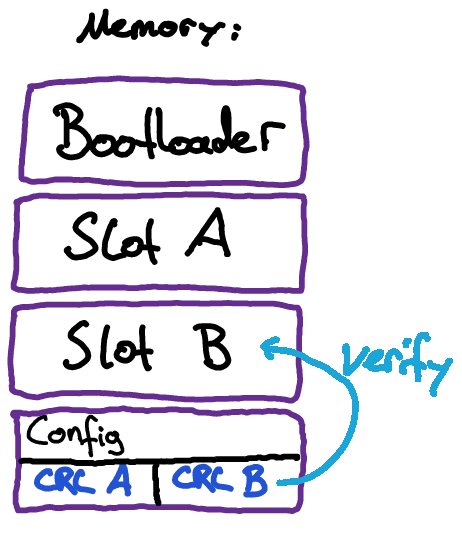
Storing the application
When it comes to storing the application payload in memory, a widespread approach is to employ an A/B partition layout. Given the current application is located in slot A, an update is stored into slot B. If the update process is successful, the bootloader flips a switch in a persistent configuration memory and subsequently boots into slot B. Otherwise, the application payload in slot A is still intact so the device can keep operating on the old software version.

It is straightforward to see how the A/B scheme can effectively improve reliability. This can be of great importance when it is expensive to distribute updates, e.g. because of low bandwidth wireless networks. In our case however, the device is always connected to the SPARK via Ethernet, so pushing updates is comparably cheap.
Therefore, we opted for the simpler approach of managing only one application slot in memory. In case of an update failure, there is no valid application anymore so the device just sits in the bootloader and waits for a new update to be pushed. Not only can the update logic be kept simpler, compiling an application for this system also becomes easier because there is no relocation required. But more on that later.
Verification
After a new update has been transferred and programmed into memory, a CRC checksum is calculated on the entire payload and checked against the checksum generated by the updater application on the SPARK. This is to catch any problems during transmission or programming. Furthermore, the checksum is saved in a configuration memory space to verify on every boot that the application is still intact.
Wrapping up
In this post, we discussed the overall design of an embedded bootloader that enables OTA updates on microcontrollers. A key component to make the system more resilient is a hardware watchdog that resets the whole system whenever it hangs. Furthermore, checksumming can be used to make sure that an update is transferred correctly as well as it doesn’t corrupt over time.
What is left now is a mechanism to trigger an OTA update when an application is loaded since only the bootloader can accept updates. By our design, this boils down to resetting the system to get a short window of opportunity during which an update can be pushed to the bootloader. However, this can vary considerably among use cases and thus is not in the scope of the bootloader.
The next post in this series will be about flash memory and introduce you to linker scripts. Stay tuned!
TL;DR
- after reset, small window of opportunity for updater to upload new application
- A/B partition vs just one application image
- configuration memory: partition CRC, active partition (A or B)
- verify checksum of application before starting it
- if an update is to be flashed, application must reset the system to get into bootloader
- use hardware watchdog to recover from unforeseeable failures